Vapor degreasers use a closed-loop system that works very reliably and efficiently as long as it is set-up correctly. If not, you can experience solvent loss, equipment corrosion, loss of cleaning performance, etc.
By now, your process team has studied the placement area of the unit as well as performed the basic operational checks and has become thoroughly familiar with the controls and functions. For review, see the first two parts of this series that cover these subjects:
- Finding the Best Location for Your Vapor Degreaser
- Key Operational Checks When Setting Up A New Vapor Degreaser
Before you perform the optimizing process, it is important to note the following:
- This should be performed on each different part you clean. This will help you develop SOP’s that your operators can follow.
- A subset of this is to develop a program for each different soil on the parts. As an example, you may be a contract manufacturer that utilizes a large number of solder pastes and fluxes depending on the requirements and call-outs of your customer.
- Determine, by the construction of the parts, what you can and cannot utilize of the various cleaning options of your unit based on the sensitivity of the components. For instance, what is allowed by the customer – immersion (boil or clean/cold sumps), ultrasonics, wand usage, etc.? Some customers may leave it up to you to determine the best and most efficient method while others will tell you what is not allowed or not recommended due to the sensitivity of the components. For instance, RF components generally cannot withstand the aggression of an ultrasonic process due to their sensitive frequency operation.
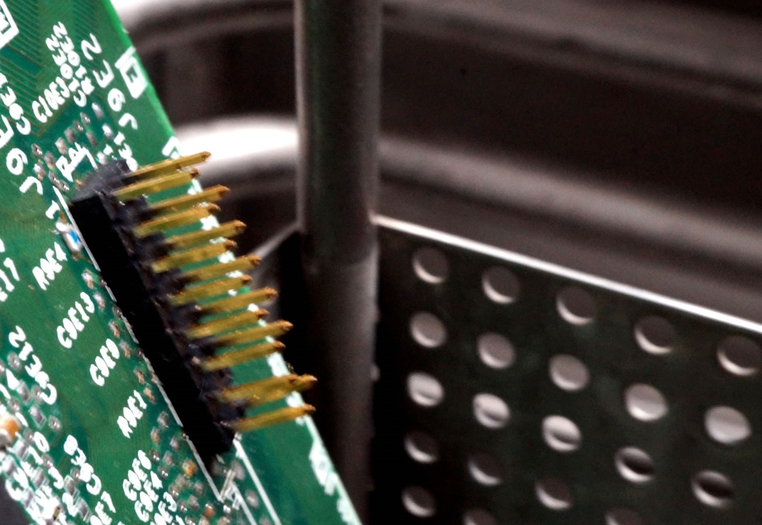
As our example, we will use a basic PCB to be defluxed with no sensitive component restrictions. However, also assume the customer has specified that there will be no immersions, i.e. vapor zone cleaning, but spray wand usage is OK.
Hopefully, your chemical manufacturer has performed cleaning trials on these test boards and has provided you with a general guideline for vapor zone cleaning only. Use these settings as a starting point. If this has not occurred, you will need to start from scratch.
Step 1: Optimize for Maximum Condensation
- Run the test board with a standard vapor zone cycle time to assure that maximum condensation has occurred (when condensation stops, the part and the vapor have reached the same temperature and will be essentially dry). Record this time.
- At this point, cleaning has ceased. Remove the part following the withdrawal procedure and inspect for cleanliness. If there is remaining flux residue, the cycle must be repeated.
- Re-insert the part next to the cold condenser to chill it as much as possible to obtain a wide temperature delta between the part and hot vapors (record this length of time for future reference).
- Again, lower the part into the hot vapors and record this time (it will probably vary a bit from the first cycle).
- Go through the withdrawal procedure and again inspect the piece. If it meets the cleanliness requirements, you’re done. If not, repeat the cycle until clean.
- Verify the vapor zone cleaning procedure based on your specific validation plan.
Step 2: Evaluate Supplemental Cleaning Steps
Since there was no restriction on wand usage, now test this along with the times recorded for vapor zone cycles.
- Start with using the wand (record the time of spraying) prior to the vapor zone cleaning and see if that makes an improvement.
- Increase the spray times a bit prior to vapor immersion to see if cleaning improves. If not, start decreasing the times to find the maximum cleaning in the shortest time.
- Also, try the wand spray in the same manner at the end of the vapor cycle times.
- Record all of these spray wand variations and times to be compiled later.
The idea behind this simple example is to increase cleaning performance in a timely manner to increase throughput, decrease solvent loss, and operate the unit in an efficient manner.
For each cleaning option/variable you try, if the option does not add in the cleaning performance or in reduced time, discard it. At each stage of the experiment, go back and re-verify each until you are convinced that the process is operating flawlessly and with maximum performance.
Obviously, you can see that if you have multiple parts and soils, this can take a long period of time to set up your cleaning programs or schedules. However, once done, your operators will have a clear step-by-step recipe for the variations in parts and soils. Each time a new one is added, the validation process must be repeated and an addendum made to the program to follow.
Essentially, any time the upstream process changes, the “cleaning department” should verify what, if any, changes should be made to account for this. This will give your process team members confidence that the cleaning method was validated by a strict set of rules and the most efficient method was chosen to meet customer performance standards as well as utilizing production time wisely. It is well worth the time spent in optimizing and recording the process. Your customers and team members will appreciate the results.
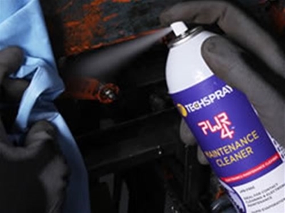
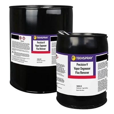
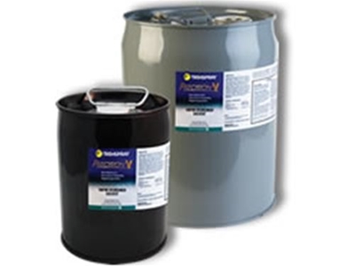
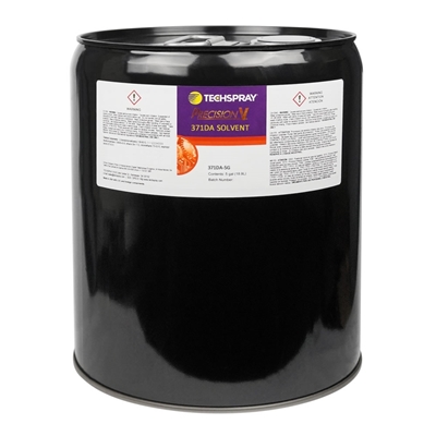
TECHSPRAY VAPOR DEGREASER SOLVENTS
Techspray has a large variety of solvents intended for vapor degreasing under the brand names PWR-4™ and Precision-V™. These products are engineered to be less toxic than many other solvents commonly used in vapor-degreasers: e.g. TCE (Trichloroethylene, CAS #79-01-6), nPB (n-Propyl Bromide, CAS #106-94-5), and Perc (Perchloroethylene, CAS #127-18-4).
Techspray has technical resources to help you evaluate and set-up your vapor degreaser machine. Contact us or give us a call at 770-424-4888 to get started.
Resources