The increased miniaturization in modern electronics has been continuously reducing the pitch between conductors and increasing the probability of electrochemical migration of contamination in class 3 electronic devices. Contamination, if not taken care of properly, can cause serious reliability issues in electronics involved in mission-critical applications.
The quest for contamination-free electronics requires adherence to strict cleaning standards. Accordingly, to qualify the electronic cleaning process, established cleanliness testing methods are necessary. Furthermore, the choice of cleanliness testing method determines the quality and reliability of the device in the long term.
This article provides insight into electronic cleanliness testing methods. For better awareness, the article first discusses a test vehicle and later draws comparisons among different cleanliness testing methods. To enlighten the readers, the choice of cleanliness testing methods for specific applications is discussed in the form of case studies. To aid electronics manufacturers, the article concludes by mentioning Techspray’s cleanliness qualification testing lab.
Test Vehicle Design
An efficient and cost-effective test vehicle (TV) must address the following issues:
- Material Qualification
- Process Qualification
- Representative of actual product
- SIR test vehicle
- Ion Chromatography coupon
- Solder mask adhesion coupons
- SIR mini-coupons for evaluating raw board cleanliness
Similar to modern electronics, this TV passes through reflow ovens twice as it has components on both sides. The complex board has plated through-holes (PTHs), wave-soldered connectors with SIR patterns, and low standoff components (e.g., PQFP package (0.4 mm)) all of which increase the potential for flux entrapment and difficult reworking sites. Figure 1 shows the IPC-B-52 TV. For other application specific TVs, the reader is urged to read the article on Comparison of Test Vehicles.
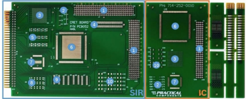
IPC B-52 test coupon comprises a SIR test coupon (SIR) and a section for ionic contamination measurements (SIR). Component ID:1 – TH connector 4 x 24 pins; 2 – Capacitor, 10 pF, 0402 package; 3 – BGA, 256 IO, 1mm pitch, isolated; 4 – sm connector IEEE 1386, 2 x 16 pins; 5 – Capacitor, 10 pF, 0805 package 6 – QFP160, 065 mm pitch, isolated; 7 – QFP80, 0.5 mm pitch, isolated; 8 – Capacitor, 10 pf, 0603 package; 9 – SOIC16, 127 mm pitch, isolated; 10 – Capacitor, 10 pF, 1206 package.
Figure 1: IPC-B-52 TV [2]
Electronics Cleanliness Testing Methods
Visual Inspection
An obvious indicator of an improperly cleaned PCB is the presence of white residues on its surface. The activators present in no-clean flux residues, if not cleaned, may transform to white residues (haze like material) when exposed to heat or other chemicals. If the cleaning process is already tested and qualified, the visual inspection can serve as a process control method.
Visual inspection is the first and the cheapest method of cleanliness testing which requires only two human eyes to identify any white residues, dendrites, or any visible flux. Though this method is only qualitative and not very elegant, it works well for class 1 electronic devices.
The IPC-A-610 indicates that the cleanliness inspection can be conducted without magnification (with bare eyes). However, magnification could be required for "high density boards" and fine-pitch components. IPC specifies magnifications up to 20X which still may not suffice for viewing very fine trace residues. In that case, IPC suggests magnification of 40X as the ‘referee’ magnification [3].
ROSE (Resistivity of Solvent Extract)
As the name suggests, in this method a solvent (75% Isopropyl Alcohol and 25% deionized water) is used to extract the ions (any present on the PCB). The extraction method might be dynamic, static, or manual. This is also called Omegameter testing [4] but it does not provide precise results.
In the ROSE method, the boards are immersed in the solvent which is allowed to circulate around the components. The solvent dissolves ions and salts from the boards. The final resistivity of the solvent itself, with any dissolved contaminations, then measures the cleanliness (or dirtiness) of the board. The change in resistance in the solvent (measured by Omegameter) between the initial and the final solution quantifies any ionic contaminants. The ionic results are represented as “micrograms of NaCl equivalent per square inch”. The IPC standard for a clean board requires the ionic test result to be < 6 μg NaCl eq./in2.
The ROSE method has some inherent limitations including:
- It cannot identify the types of contaminants (residues), hence it can only be used in process control and not for cleanliness process qualification.
- The measured contamination is averaged over the whole surface of the PCB.
- Inability to identify a small amount of localized contamination.
- Inability to detect weak organic acids (WOA) left by no-clean fluxes. In fact, the exposure of no-clean flux residues (if not cleaned) to alcohol may produce white residues, negatively impacting the PCB’s health.
To further emphasize the second and third points above, a case study [5] investigated the root cause of failure of a PCB with localized dendritic growth (between two vias) and electrical failure. In this case study, the ROSE test indicated an acceptable level of cleanliness even though the board malfunctioned.
SIR (Surface Insulation Resistance)
Current leakage, dendrite formation, and electrochemical migration are all the results of contamination, which eventually affect the surface insulation resistance of the PCB. The SIR test is used to measure the conductivity of leftover ionic residues. The result of a SIR test is a resistance offered to the flow of charge across traces caused by conductive contamination. Higher resistance (ideally infinite) is an indication of a clean board.
To realize long copper tracks in a minimum space, special comb-like test patterns are used in SIR testing. After cleaning, solder paste/flux is applied to test coupons. As outlined in IPC J-STD-004B, SIR testing is performed at 85% relative humidity (RH), 85oC temperature, in the presence of a 45-50V DC bias and a reverse bias voltage of 100V [6]. These conditions (set in the calibrated environmental chamber) accelerate electrochemical migration and dendrite formation in the test coupons. The test procedure takes 7 days to complete and the pass criteria is a reading of a minimum of 108 ohms from the 4th day onwards [6]. The main limitations of this method are:
- The long time it takes to complete the test.
- The requirement of test vehicles (rather than the actual product).
- For SIR test to be meaningful, the residues have to be between the comb patterns.
- The accelerated conditions can change the phase of residues which makes the results of this test questionable.
Ion Chromatography (IC)
IC is another test that uses the method of solvent (IPA + DI) extraction. The residues present in the unit under test (UUT) are dissolved in the solvent. The chemistry of the extracted solution is determined using ion exchange resin. The added advantage of IC over ROSE is its ability to separate out ions, their types, and concentrations. The result of an IC test is a graph of ionic concentrations (per square inch) vs time.
The ionic residues that most often originate from solder fluxes and pastes include Sodium (Na+), Potassium (K+), Chloride (Cl-), Bromide (Br-), and WOAs [6]. The presence of a particular ion on the PCB indicated by IC may help the process engineer to diagnose the root cause of problems.
Assume that the IC detects the presence of chloride ions Cl- on the PCB. Two possible sources of this ion may be:
- The etching solution for PCBs use Chloride Copper + Hydrochloride + water + Hydrogen Peroxide (alkaline etching solution), and if not rinsed properly, chloride ions may remain on the PCB. This calls for optimizing the cleaning process.
- Another source of chloride ions is the solder flux left after soldering. In order to promote strong solder contacts, chlorinated compounds were added to solder fluxes (though current no-clean fluxes don’t use halides).
- If magnesium ions are detected, this might indicate that the rinsing water was not deionized which calls for improving rinse water quality. In fact, the rinsing water contained magnesium ions and hence the IC result shows a peak at Mg+2.
- The presence of bromide ions (Br-) may indicate under-cured resist. Bromide ions are also present in the fire-retardant material used in laminates and solder masks [6].
- Similarly, the presence of WOAs may indicate presence of flux residues on the board or the water used is contaminated (tap water instead of DI water). The presence of flux residues might also indicate that flux had not received full heat during wave soldering.
- The appearance of sulfur and barium ions in the IC test may indicate a decomposed solder mask.
The benefit of the Ion Chromatography (IC) test is that it can identify and quantify weak organic acids (WOAs). Conventional WOAs found in no-clean flux include Di-carboxylic acids like adipic, glutaric, succinic, and malic acids. These WOAs leave behind charged residues on the board’s surface that are hygroscopic in nature. The main limitation of this test is its total solvent extraction method (instead of localized extraction) which causes the test to average out the measured concentration over the whole board area and quantifying localized contamination is not possible with this test [7].
Local Ionics Test
As the name suggests, this test focuses on a specific area of approximately 0.1 in2 or less. In addition to the quantity and type of ionic contaminants, this test provides meaningful results because it can identify the areas of PCB affected by contamination. The removal of ionic residues is carried out in 3 steps [8]:
- Heating the extraction solution
- Soaking to enable dissolution of ions
- Drawing the solution in a collection cell
The extraction cycle is repeated 9 times. A bias voltage (10 V) is applied to the extracted solution with the help of electrodes. If the current through eluent exceeds 500 μA within 120 seconds, the region is declared as dirty [8]. This type of localized ionic test is used in devices that fall under class 2 & 3 electronics category. Particularly, this test is best suited to test cleanliness under low stand-off components because of its localized or “site specific” extraction method. This is shown in Figure 2. The local ionic test performs independently of the dimensions of the board and the result is consistent across various geometries of PCB.
Figure 2: Localized extraction method (under SMT low stand off area) [9]
Built-in ROSE Type Testing
In a batch cleaning system, performing a ROSE test on every board in the lot is not practical and hence it is not possible to ensure reliability of boards at an individual level. However, to approximate the best results for real-time feedback, some manufacturers of batch cleaning machines have given a provision to include a built-in ROSE test.
This built-in ROSE test is performed between final rinsing and drying sections [10]. However, the built-in ROSE test is not the actual ROSE test as per IPC standards. The major difference between the built-in ROSE test and IPC ROSE test is the solvent. While IPC recommends using a volume of IPA and DI, the built-in ROSE tester uses DI water only.
The reason these manufactures specify excluding IPA relates to the formation of white residues when no-clean flux residues interact with IPA. According to them, DI water alone cannot form white residues on interaction with no-clean flux residues. However, the drawback of this modification is the insolubility of rosin-based flux residues in DI water alone. Rosin-based flux dissolves readily in IPA and hence the IPC standard of 75% IPA and 25 % DI is justified.
Moreover, the introduction of a built-in ROSE test is employed as a process control tool only. In simple words, built-in ROSE tests measure the resistivity of the rinsing water only (not the actual contamination on the board) and hence it cannot pass or fail the cleaning process based on its result.
In some machines, a built-in resistivity controller automatically adjusts the cycle time until a preset resistivity level is attained. The reader must keep in mind that it is a misconception to consider this built-in tool as an IPC-approved method of ionic contamination testing.
Which Cleanliness Test Performs Best?
One case study [8] compared the different methods discussed above. PCBA test vehicles (TVs) were prepared using different solder pastes, no-clean fluxes, and each test vehicle was reworked differently than the other. The TV is shown in Figure 3. Details of TV components are shown in Figure 4.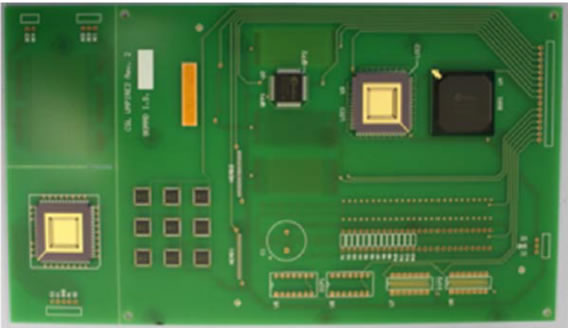
Figure 3: TV top side layout [8]
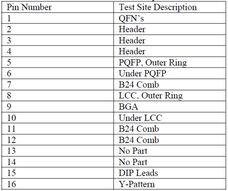
Figure 4: TV description [8]
 |
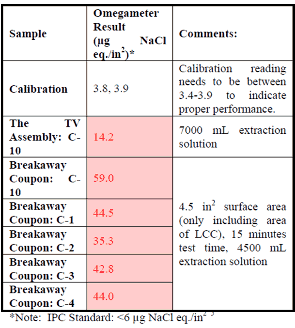 |
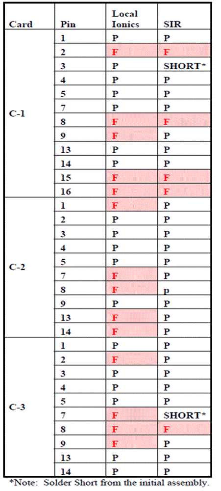
Figure 5: SIR vs Local Ionics vs ROSE Test for a group of TV [8]
The results in Figure 5 indicate that localized ionic and SIR testing have a 76% correlation when both tests have a matching pass or fail result [8]. ROSE tests for all the tested samples failed because no-clean fluxes leave immobilized ionic residues, rendering the ROSE test irrelevant. Another group of TVs were tested to draw a comparison between local ionic test and IC. The results are summarized in Figure 6. IC correlates 100% with local ionic test. This has been proved in another case study [6].
Therefore, it is not wrong to say that the local ionic test performs well compared to SIR and IC and so this test should be preferred in analyzing localized contamination or for low stand-off components (especially class 2 and 3 electronic devices). Mere ROSE testing may not suffice in detecting localized contamination in sensitive advanced electronic components [6]. The best practice may be to utilize local ionic tests to know the conductivity of ionic contaminants followed by IC to identify the chemistry of the contaminants [6] and root cause of failure.
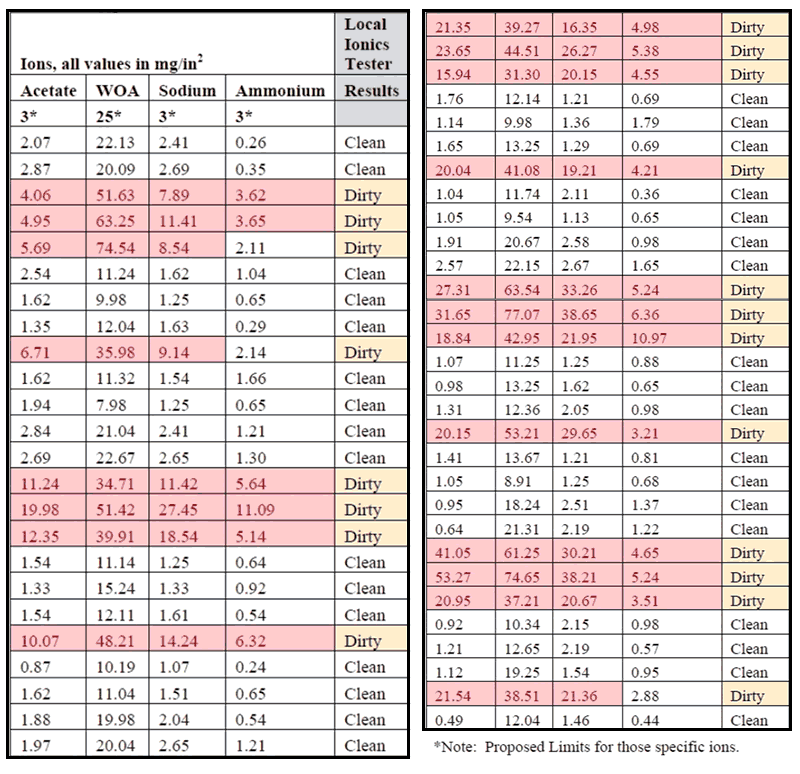
Figure 6: Local Ionics Test vs IC [8]
Techspray – Let’s Work Together to Optimize Your Cleaning Process
With over 30 years of successful business worldwide, Techspray possesses a unique perspective on cleanliness and cleanliness testing processes. Techspray’s TechLab offers state-of-the-art cleaning, coating and analytical services to help customers optimize their processes. Our cleaning equipment includes batch, ultrasonic, and vapor-degreasing systems. This equipment allows us to better duplicate your production environment for process optimization and troubleshooting, while ensuring compliance, safety and affordability. Depending on your needs, whether it be cleaning or identifying a problematic process or product, or to identify a product to assist your normal processes, our staff, equipment and expertise are here for you.
Contact Techspray for free TechLab qualification testing. We are available to help qualify new cleaning processes, evaluate current processes, or troubleshoot contamination issues. We can test actual production samples or use our specially designed cleanliness testing board. For more information, contact your Techspray application specialist at 678-819-1408 or [email protected].
References
[1] M. K. W. M. N. R. Mitchell Ferrill, "THE IPC-B-52 SIR TEST VEHICLE: A DISCUSSION OF THE CURRENT TEST VEHICLE DESIGN AND POSSIBLE MODIFICATIONS FOR THE FUTURE," in SMTA International Conference, Orlando, 2012.
[2] K. Tellefsen, "Divergence in Test Results Using IPC Standard SIR and Ionic Contamination Measurements," I-Connect007, 01 08 2016. [Online]. Available: https://smt.iconnect007.com/index.php/article/99083/divergence-in-test-results-using-ipc-standard-sir-and-ionic-contamination-measurements/99086/?skin=smt. [Accessed 01 04 2023].
[3] E. LC, "PCBA VISUAL INSPECTION / IPC-610 INSPECTION / GMW3172," Elmet LC, [Online]. Available: https://www.elmetlabs.com/printed-circuit-board-assembly-visual-inspection#:~:text=610%20Inspection%20%2F%20GMW3172-,IPC%2DA%2D610%20is%20the%20industry's%20most%20widely%20used%20visual,component%20placement%2C%20and%20board%20cleanliness.. [Accessed 28 03 2023].
[4] I-Connect007, "The Effectiveness of 75% IPA/25% DI Extraction Solution on No-clean Flux Residues," I-Connect007, 13 06 2019. [Online]. Available: https://smt.iconnect007.com/index.php/article/117790/the-effectiveness-of-75-ipa25-di-extraction-solution-on-no-clean-flux-residues/117793/?skin=smt. [Accessed 14 2 2023]
[5] T. Munson, "Comparison of Testing Methods for Residues on Electronic Hardware," [Online]. Available: chrome-extension://efaidnbmnnnibpcajpcglclefindmkaj/https://static1.squarespace.com/static/5ddd523267a1ae54e9d2cb96/t/60b67ba6f1d6ef0e78196637/1622571945474/foresite-comparison-of-testing-methods.pdf. [Accessed 31 03 2023].
[6] R. J. J. A. K. D. Kong Hui Lee, "Comparison of ROSE, C3/IC, and SIR as an effective cleanliness verification test for post soldered PCBA," Soldering & Surface Mount Technology, vol. 23, no. 2, 2011.
[7] P.-E. &. D. B. D. Tegehall, "Evaluation of Cleanliness Test Methods for Spacecraft PCB Assemblies," Evaluation of Cleanliness Test Methods for Spacecraft PCB Assemblies (ESA STM-275). P.-E. Tegehall, B.D. Dunn. Editor: B. Battrick. ESA Publications., 2006.
[8] J. P. D. B. T. M. Phil Isaacs, "Comparison of ionic contamination test methods to determine their ability to reliably predict performance risks," in 2017 Pan Pacific Microelectronics Symposium (Pan Pacific), Kauai, 2017.
[9] Foresite, "Want to find out if your PCBAs are clean?," Foresite, [Online]. Available: https://www.foresiteinc.com/products. [Accessed 30 03 2023].
[10] A. A. Technology, "AAT," AAT, [Online]. Available: https://aat-corp.com/2020/11/23/what-is-rose-testing/#:~:text=In%20many%20cases%2C%20deionized%20water,both%20batch%20and%20inline%20cleaning.. [Accessed 01 04 2023].